Around a month ago, I met an engineer from an EEG sampling system company. I asked him many specifications of their circuit. He told me that they only amplify the EEG signal by 20 or 30 times and then feed it to a 24-bit ADC. Besides noise issues, did not understand why they chose high-resolution ADC over high-gain amplifier. Today I learned a lesson and figured out.
I am using NI myDAQ these days to test the amplification (very high gain, expected to be 10,000 or 80dB) circuit I prepared for ECG data acquisition project. Of course, Bode plot is what I used to the check the gain and phase shift.
 |
| My configuration. The chip on the left is an TI OPA177 used to divide the input voltage of INA128 to as low as 1mV. The minimum resolution of the Function Generator of NI myDAQ is 10mV and I wanted the signal amplitude to be as low as raw ECG. The chip on the right is TI INA128, with R_G set as 5 Ohm. The output signal of INA128 is filtered by an RC bandpass filter and then goes to myDAQ. There was an error in the circuit when I shot this picture. The ground of RC circuit was not grounded. |
Any analog circuit has a setting time (at least the speed of light), e.g., to reach a feedback balance. When the gain of an amplifier goes very high, the setting time increases nonlinearly. According to the datasheet (http://www.ti.com/lit/gpn/ina128) from Texas Instruments, the setting time of instrumentation amplifier INA128 is 9 us when gain is 100 while 80 us when gain is 1000. The gain of INA128 ranges from 1 to 10000. But the datasheet does not say what will happen for gain larger than 1000. Why? Probably because the setting time is very long and varies from device to device.
This is like many bivariate constraints in analog circuit design, e.g., gain-bandwidth product. Therefore, in Bode analysis, it needs to wait significant long enough time before you can measure the output and move the next frequency.
But the Bode Analyzer that comes with NI myDAQ (also used on NI ElVIS II/II+), does not give the circuit enough setting time. The software measures the output before the circuit can settle down from the input stimulus.
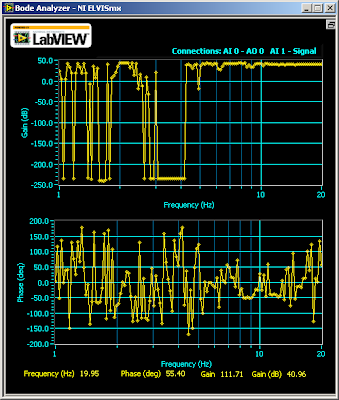
What happened was, when gain is 1000, I saw this
I said, what? Where are my signals over 14 Hz? But when I increase the gain to 5000 (well, from myDAQ's oscilloscope which now I assume has errors too because the theoretical gain for my configuration is 10,000.), I was thinking to withdraw this class:
The gain was constantly high before 10 Hz and dropped drastically after that. The phase shifting plot looked like stock market after that. According to the datasheet of INA128, the gain should not drop before 1kHz.
Why? Now I know the answer, because the Bode Analyzer did not wait until the circuit to stabilize. It measured unstable output. As the gain goes higher, more waiting time is needed.
But at that moment, I did not think about this. I tried another way to study the problem, using other instruments. I checked the waveform on the Oscilloscope of NI myDAQ while letting the Function Generator of myDAQ sweep from 1 Hz to 20Hz, with a step of 0.5 Hz. And, I let the signal stay at each frequency for 3 second, way enough for the circuit to stabilize. By comparing the Vp-p on the oscilloscope, I saw that my circuit wasn't as bad as the Bode plot showed. It was as designed.
Below is a video I took when the Function Generator swept. I didn't save the original video for the output from INA128. Instead, I recorded the output waveform from an RC bandpass filter following the output of INA128 (blue line). The green line was the input to INA128. I set the cutoff frequency of the RC filter at 15Hz (which is not exact because the discrete components have 5% error each). As you can see, the signal drops gradually after 8Hz but not at a >100dB attenuation. Also, the phase shift wasn't as crazy as stock market. The shift was almost invisible. Of course, I need to fix the circuit because apparently, the -3-dB point was at 22Hz (not shown on the screen as I ended the screencast early).
So, go back to my question, why medical instruments prefer high-resolution ADC over high-gain amplifier, besides noise issues. Well, a high-gain amplifier takes long time to stabilize (INA128 takes 80us to set at G=1000), then the sampling rate cannot be high (for INA128, sampling rate can not be higher than 10kHz when G=1000). The setting time for amplifiers at high gain, is longer than the setting time of a high-resolution ADC (which can handle MHz signal).
PS: Another interesting thing is that Bode Analyzer of myDAQ gave me this for TI INA101:
I would like to know whether INA101 is really bad from 1 to 10 Hz or it's another problem of the Bode Analyzer of myDAQ.


No comments:
Post a Comment